ESU Products |
(Click your browser's BACK button to return to the product listing)
|
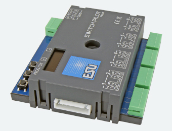
| ESU51831
SwitchPilot 3 Plus, 8x accessory decoder, DCC/MM, OLED, updatable NOTE: For the most current instruction sheet consult the ESU website directly. SwitchPilot 3 Plus decoders are optimized for stationary use on your system and can switch conventional double coil switch drives, light signals, magnetic uncouplers, light bulbs or other stationary consumption. In order to facilitate the rather cumbersome configuration of magnetic article decoders, the SwitchPilot 3 Plus has an innovative operating concept consisting of a 4-line, illuminated OLED display and three input buttons. The SwitchPilot 3 Plus is multi-protocol and can be used with control panels according to the Märklin® Motorola® system (e.g. 6021, Central Station® or Mobile Station®) as well as DCC-enabled control panels. The configuration can take place on both the main track and the programming track. Thanks to RailCom®, CVs can also be read out. The SwitchPilot 3 Plus can be supplied directly from the digital system or from an external DC or change voltage source. It has a total of 16 transistor outputs, which are grouped in the 8 exit pairs 1 to 8. Each output pair contains two outputs (OutA and OutB) and can be configured individually for the desired use case: In pulse mode, the output is switched on as soon as a switching command is received. Since the output automatically switches off again as soon as a time stored in the decoder has been reached, a burn-through of magnetic articles is prevented. At the moment (K83-compatible) the output remains active as long as the button on the control panel is pressed. This operating mode is suitable for turnout drives with final shutdown or for de-caps. In bi-stable continuous operation (k84-compatible), the two outputs are switched on and off: When pressing the first button (red) on the control panel, the output Out A is switched on. It remains active until pressing the assigned button (green) activates the output Out B of the same output group. Out A and Out B behave like a change switch.In alternating flasher mode, the outputs Out A and Out B of an output pair are switched on alternately with an adjustable flashing frequency. The change indicator is started with the command "Gerade/Green" of the assigned button and stopped again with the command "Branching/Red". Optionally, the output can also be slowly dimmed and dimmed (so-called "zoom" for incandescent lamp simulation). The SwitchPilot 3 Plus can be flexibly adjusted either on the programming track with DCC control panels or on the main track with POM ("Programming on Main") or can also be read out via RailCom® CVs. On request, he also learns the addresses directly via a programming button. The setting is, of course, the simplest with the integrated OLED displays as well as the three input buttons: All (!) Settings can be checked directly on the decoder and changed on request. "Programming" with the help of your headquarters is not required. It really can't be any easier. The ESU LokProgrammer can be used for firmware updates. As with our locomotive decoders, the outputs of the SwitchPilot 3 Plus are protected against overload. We want you to enjoy your decoder for as long as possible. |